Nampaknya tahun 2009, boleh relax sikit pasal Oil and Gas industri dijangka tak sesibuk tahun-tahun sebelumnya. Ini dapat memberi peluang kepada designer dan drafman menilai diri.
Adakah cukup ilmu sebagai designer atau drafman? Atau menjadi designer atau drafman sekadar memenuhi kehendak industri. Ada ot belasah cukup-cukup, dapat offer tinggi lompat, kerja macam nak rak janji dapat lebih.
Adakah sama taraf kita berbanding dengan pare-pare dari segi technical knowledge.
Adakah knowledge yang ada setaraf dengan designer muktabar?Sekiranya kita merasakan kita designer yang terbaik.
Adakah pemikiran kita pada tahap pemikiran designer,menilai sesuatu mengikut penilaian designer,andainya kita designer.
Jika kita drafman, adakah kita telah megutip knowledge yang ada untuk bekalan jika menjadi designer esok hari? Atau hanya berserah pada takdir, lama-lama akan promote jadi designer juga.
Sepatutnya kita mendapat menafaat dari kesibukkan yang lalu untuk meningkatkan pengetahuan dan pengalaman. Tapi apa yang berlaku ialah kebanyakannya menggunakan suasana ini untuk meningkatkan pendapatan. Menggunakan peluang akibat dari kekurangan manpower dengan melompat dari satu syarikat ke syarikat lain yang dapat menawarkan gaji yang tinggi.
Pada tahun 2009 jika keadaan ekonomi berlarutan, syarikat akan mengekalkan pekerja yang mempunyai kemahiran dan akal didalam organisasinya. Minta maaf kata pekerja yang gaji tinggi akan dinilai semula mengikut keperluan. Syarikat akan optimise manpower sebaik mungkin.
Walau apapun banyak-banyak lah berdoa dan beribadat sesungguhnya rezeki itu Allah yang bagi bukan syarikat tapi ilmu kita kena cari..
Wednesday, December 31, 2008
Sunday, December 21, 2008
GIVE CONSTRUCTIVE FEEDBACK
GIVING feedback is one of the most important interpersonal skills for any manager.
The purpose of constructive feedback is to provide information that will contribute to improvements and create better results.
For feedback to be useful, it has to be actionable, otherwise it's likely that the situation or behaviour will recur.
Whenever you are giving feedback, keep in mind that you'll probably have an ongoing relationship with this person, so use your feedback to reinforce good relations.
Let's say that you're giving constructive feedback to a member of your staff. Here are five steps to help you give good feedback:
1-TIME IT RIGHT
Make sure the time is right. The sooner the better, but if you're upset about the situation - or your employee is - take a "timeout”. This is preferable than giving or receiving feedback when one of you is already in a bad mood.
2-CHOOSE YOUR WORDS
The way you say something can have a great impact on the listener. Depending on your choice of words, you can establish an amicable feedback environment or a hostile one.
Saying, "You need to do..." or "You're not doing this properly," can put the receiver on the defensive from the get-go. Using the pronoun "you" makes the comments personal and can be interpreted as condescending or highly critical. Instead, say "I noticed that..." or "I understand that..." Beginning feedback phrases this way discusses the action or behaviour that needs to be changed, not the person.
3-BE POSITIVE
Positive feedback acknowledges good contributions and work well done. Give specific examples of what the person did well.
Doing so is more meaningful than a general "Good job!" comment that can be said to anyone, any time, and doesn't even have to be sincere.
Let the receiver know the positive impact his contributions had on the department or organisation so he understand the results - this also lets him know that you see it and appreciate it. In addition, reinforcing the positive encourages more of the same.
4-BE DESCRIPTIVE
When giving constructive feedback, discuss what happened, not how you feel about what happened. Focus on the situation, describe it, and stay objective.
Give a reason why it's an issue and state the impact it had on the rest of the staff, the organisation or the customer.
When you stick with the facts, you can discuss them more easily. Being specific and clear assists the listener in understanding the issue and what requires changes.
5-COLLABORATE
It's not up to you to come up with all the solutions by yourself, although you can offer suggestions that you think would be helpful.
Make a point of involving the recipient in this crucial part of the feedback process.
This way, the recipient has some ownership and involvement in decision-making, which will result in a greater commitment to see that it's implemented.
Working together finds better ways of improving the situation and will likely create a solution that is acceptable to both of you.
Offering constructive feedback can seem like a daunting task. If it is approached with the intention of making improvements and creating better situations, rather than criticising and judging, it is positive input that gets beneficial results.
- The Star 20-12-2008
-Source: ST/ANN
Article by Laurie Wilhielm, the author of Express Yourself to Success.
Wednesday, October 22, 2008
Develop A Winning Attitude
Your qualifications may get you a job, but good performance is what makes a successful career
THE job market has traditionally rewarded those who have made the extra effort in school with higher compensation and better opportunities for advancement.
THE job market has traditionally rewarded those who have made the extra effort in school with higher compensation and better opportunities for advancement.
But there are signs that this attitude may be changing. As the expression goes, “one’s qualifications (ability) get one hired, yet one’s performance (attitude) results in one being fired”.
It is crucial to understand that possessing good qualifications is a prerequisite for any career to soar.
But it is your attitude towards your job, colleagues, clients and superiors that is a far more important and accurate determinant-of performance and advancement.
The lack of professionalism at work is not easily raised and discussed as it involves the emotional intelligence of the person.
Superiors generally gloss over these issues and simply do not promote the individual.
REALITY CHECK
To take your career sky-high, your first challenge is to do a reality check. Ask yourself:
• How much am I doing to keep abreast of developments in my field?
• How much am I investing in my own development?
• How competent am I when engaging with others?
• What is my overall attitude to those whom I serve, work with and report to?
BENEFITS OF WORK
The workplace offers intrinsic benefits like career development, in terms of skills learned, social interactions, financial discipline plus other core skills such as computer literacy. It also offers opportunities for personal development. Ask potential employers about their attitudes and practices toward training, promotions, exposure to travel and new situations, job rotation and performance appraisals. These aspects of employment will develop your skills and nurture your chaiacter. Together, these will ultimately help you carve a career that “knows no limits”.
Seek out companies with a great working environment as it cultivates in you a sense of respect and dignity, irrespective of your rank.
CAREER OR JOB?
What differentiates a career from a job? A career is viewed from a long-term perspective. It involves making an investment that over time is expected to yield rewards. On the other hand, a job is more transient and refers to the role you currently occupy. It is driven by the attitude of “what’s in it for me?” Great careers create a sense of passion and pride in people. When you make the-size of - the wage p?cket a priority, you usually sacrifice other important and beneficial aspects of the job that are crucial for your ‘development and progress.
What differentiates a career from a job? A career is viewed from a long-term perspective. It involves making an investment that over time is expected to yield rewards. On the other hand, a job is more transient and refers to the role you currently occupy. It is driven by the attitude of “what’s in it for me?” Great careers create a sense of passion and pride in people. When you make the-size of - the wage p?cket a priority, you usually sacrifice other important and beneficial aspects of the job that are crucial for your ‘development and progress.
TAKING RISKS
If you are looking for a career that has no limits, you must be willing to take some risks. Careers that are fulfilling and exciting involve challenges, taking responsibility, being empowered, being accountable and, where necessary, taking appropriate risks.
Many people look for positions that are secure and pay a reasonable wage, and are then content to go with the flow. The trouble with most streams is that they flow downwards.
Instead, Look for employment that forces you to swim against the tide, make you think, and allows you the opportunity to engage with others who are different and even difficult.
WHAT’S YOUR VISION?
Write down a three-year plan of how you want to develop.
• Your career -what are your personal aspirations and hopes regarding promotions and increased authority?
• Academic skills - what courses and types of training will further enhance your hard skills?
•Social skills and network how will you expand your circle of friends and contacts as well building skills?
• Your finances - what are your objectives and how will you achieve them?
LOOK INTO THE FUTURE
Finally, to turn your hopes and dreams into reality you need to reflect on where you want to see yourself in the next three years. Your plan provides a road map of the way forward you have to do the driving.
Finally, to turn your hopes and dreams into reality you need to reflect on where you want to see yourself in the next three years. Your plan provides a road map of the way forward you have to do the driving.
Not everything will work according to plan, but at least you have a blueprint that tells you when you are going off course. This gives you a head start over others who do not have a clue where they are going.
Source: ST/ANN
Source: ST/ANN
• Article by Steve Murphy, associate director; Training Edge international.
• For more on jobs, please refer to category 515 in Metro Classifleds and StarJobs in / StarTwo.
• For more on jobs, please refer to category 515 in Metro Classifleds and StarJobs in / StarTwo.
Wednesday, August 6, 2008
Category 5 cable
Category 5 cable
From Wikipedia, the free encyclopedia


From Wikipedia, the free encyclopedia

Cat5 patch cable
Category 5 cable, commonly known as Cat 5 or "Cable and Telephone", is a twisted pair cable type designed for high signal integrity. Many such cables are unshielded but some are shielded. Category 5 has been superseded by the Category 5e specification. This type of cable is often used in structured cabling for computer networks such as Ethernet, and is also used to carry many other signals such as basic voice services, token ring, and ATM (at up to 155 Mbit/s, over short distances).
Usage and wiring methods
Category 5
The specification for category 5 cable was defined in ANSI/TIA/EIA-568-A, with clarification in TSB-95. These documents specified performance characteristics and test requirements for frequencies of up to 100 MHz.
Category 5 cable includes four twisted pairs in a single cable jacket. This use of balanced lines helps preserve a high signal-to-noise ratio despite interference from both external sources and other pairs (this latter form of interference is called crosstalk). It is most commonly used for 100 Mbit/s networks, such as 100BASE-TX Ethernet, although IEEE 802.3ab defines standards for 1000BASE-T - Gigabit Ethernet over category 5 cable. Cat 5 cable typically has three twists per inch of each twisted pair of 24 gauge copper wires within the cable.
Category 5e
Cat 5 e cable is an enhanced version of Cat 5 that adds specifications for far end crosstalk. It was formally defined in 2001 as the TIA/EIA-568-B standard, which no longer recognizes the original Cat 5 specification. Although 1000BASE-T was designed for use with Cat 5 cable, the tighter specifications associated with Cat 5e cable and connectors make it an excellent choice for use with 1000BASE-T. Despite the stricter performance specifications, Cat 5e cable does not enable longer cable distances for Ethernet networks: cables are still limited to a maximum of 100 m (328 ft) in length (normal practice is to limit fixed ("horizontal") cables to 90 m to allow for up to 5 m of patch cable at each end). Cat 5e cable performance characteristics and test methods are defined in TIA/EIA-568-B.2-2001.
Connectors and other information

The cable exists in both stranded and solid conductor forms. The stranded form is more flexible and withstands more bending without breaking and is suited for reliable connections with modular connectors, but makes unreliable connections in insulation-displacement connectors. The solid form is less expensive and makes reliable connections into insulation displacement connectors, but makes unreliable connections in modular connectors. Taking these things into account, building wiring (for example, the wiring inside the wall that connects a wall socket to a central patch panel) is solid core, while patch cables (for example, the movable cable that plugs into the wall socket on one end and a computer on the other) are stranded. Outer insulation is typically PVC or LSOH.
Cable types, connector types and cabling topologies are defined by TIA/EIA-568-B. Nearly always, 8P8C modular connectors, often incorrectly referred to as "RJ-45", are used for connecting category 5 cable. The specific category of cable in use can be identified by the printing on the side of the cable.
The cable is terminated in either the T568A scheme or the T568B scheme. It doesn't make any difference which is used as they are both straight through (pin 1 to 1, pin 2 to 2, etc); however mixed cable types should not be connected in series as the impedance per pair differs slightly and could cause signal degradation. The article Ethernet over twisted pair describes how the cable is used for Ethernet, including special "cross over" cables.
Electrical characteristics for Cat.5e UTP

Saturday, July 19, 2008


Friday, April 25, 2008
Cable Width Selection
Cable Tray Width Selection for Installations with 600 Volt Single Conductor Cables
National Electrical Code (NEC) Section 318-11 Ampacities of Cables, Rated 2000 Volts or Less, in Cable Trays. (b) Single Conductor Cables allows cables of identical construction and conductor material to be operated at different maximum ampacities depending on the physical placement of the cables in ladder or ventilated trough cable trays.
NEC Section 318-10 Number of Single Conductor Cables, Rated 2000 Volt or Less, in Cable Trays. (a) Ladder or Ventilated Trough Cable Trays. Doesn't cover the width requirements of ladder or ventilated trough cable tray for all the types of installations that contain single conductor cables.
This is best exhibited by cable tray width calculations for three different examples of single conductor cables in ladder or ventilated trough cable tray that are permitted by NEC Article 318. The examples are based on installations that contain 12 - 500 kcmil cables (Four - three phase - 480 volt circuits or a circuit of four paralleled conductors per phase) The 500 kcmil copper single conductor cables have 600 volt 75 degree centigrade insulation. The cable's diameter equals 1.07 inches and the cable's area equals 0.90 square inches.
Example #1 is based on the requirements in Sections 318-10(a)(2) and Section 318-11(b)(2).
Section 318-10(a)(2) states that the sum of the cross-sectional areas of the single conductor cables shall not exceed the allowable fill area in Column 1 of Table 318-10 for the appropriate ladder or ventilated trough cable tray width.
12 cables x 0.90 square inches /cable = 10.8 Square Inches
Table 318-10 - Column 1 shows that the minimum cable tray width that has adequate fill area is a 12 inch wide cable tray. The 12 inch wide cable tray has an allowable fill capacity of 13.0 square inches which slightly exceeds the installation's 10.8 square inch requirement.
Section 318-10 states that the single conductors or conductor assemblies shall be evenly distributed across the cable tray. This statement leaves the exact cable arrangement in the cable tray up to the designer. Following are two examples of installations that meet the intent of Section 318-10. The cable installation shown in Figure 1A is technically superior to that shown in Figure 1B.

The installation of the cables in the cable tray as per Figure 1A is very desirable as the cables are in an arrangement where they are equilaterally spaced. This will result in equal reactances for the circuit's phase conductors. If each of the phase conductors has the same resistance and reactance, the currents to and the phase voltages at the utilization equipment will be balanced assuming that all the loads are balanced three phase loads. Motors that are supplied with unbalanced three phase voltages experience additional heating due to the voltage unbalance. A few percent voltage unbalance can be very detrimental to the length of the motor's operating life.
For the Figure 1A and Figure 1B cable installations, Section 318-11(b)(2) states that the maximum ampacities of the cables in ladder or ventilated trough cable trays without covers is 65 percent of the values in Table 310-17
For the Figure 1A and Figure 1B installations, the allowable maximum operating ampacities (Table 310-17) for the 500kcmil conductors is 620 Amperes x 0.65 = 403 amperes per conductor (without the use of a maximum ambient operating temperature correction factor).
Example #2 is based on the requirements in Section 318-11(b)(3).
Section 318-11(b)(3)states that where single conductors are installed in a single layer in uncovered cable trays, with a maintained space of not less than one cable diameter between individual conductors, the ampacities of Nos. 1/0 and larger cables shall not exceed the allowable ampacities in Table 310-17.
Section 318-11(b)(3) defines the arrangement of the cables in the cable tray to obtain the conditions that allow the cables to carry the higher ampacities. Section 318-11(b)(3) contains permissible ampacity information and it also contains information that impacts on the cable tray width selection.
If the width of the ladder or ventilated trough cable tray is selected based on the requirements of Section 318-10 for a installation being made as per Section 318-11(b)(3), the cable tray will be of insufficient width for the intended installation.
To determine the required width of a ladder or a ventilated trough cable tray as per Section 318-11(b)(3).
Total width of the Cables -- 12 x 1.07 inches = 12.84 inches
Space between cables must be equal to one cable diameter -- 11 x 1.07 inches = 11.77 inches. Total cable tray width required is 12.84 inches + 11.77 inches = 24.61 inches.
A 30 inch wide cable tray must be used.
For Figure 2 installations, the allowable maximum operating ampacities (Table 310-17) for the 500kcmil conductors: is 620 Amperes per conductor (without the use of an maximum ambient operating temperature correction factor).
This cable arrangement will result in some unbalance in the phase currents and voltages due to the fact that the cables are not equilaterally spaced. The distances from the conductor centerlines of the Phase A to Phase B and from the Phase B to the Phase C are equal but the distance between centerlines of the Phase C conductor to the Phase A conductor is larger. The reactances for the three phases will not be equal which will result in the currents to and the phase voltages at the utilization equipment being unbalanced. If the circuits are of a length where it is possible to transpose the phase conductors, the reactances of the phase conductors can be equalized. Two transposition would allow each phase conductor to occupy each of the three conductor positions for 1/3 of the length of the run. For very long runs, it may be desirable to have many transpositions but regardless of the number of transpositions each phase conductor must occupy each of the three conductor positions for 1/3 of the length of the run.
This type of installation can only be made where the cables can be terminated without entering raceways (The ampacities in Table 310-16 must be used if the cables enter a raceway). Examples would be at a transformer secondary or at a bus extension from switchgear.
It is best to use the 75 degree C ampacity values even if a 90 degree C insulated cable is installed unless it is known that the equipment can accommodate the termination of the higher temperature conductors. For the Figure 2 installation, the 90 C insulated conductor operating at its maximum ampacity will produce 27 percent more heat than will the 75 C insulated conductor. See NEC Section 110-14(c).Temperature Limitation.
Example #3 is based on the requirements in Section 318-11(b)(4).
Section 318-11(b)(4) states that where single conductors are installed in a triangular or square configuration in uncovered cable trays, with a maintained space of not less than 2.15 times one cable diameter between the cable groups, the ampacities of Nos. 1/0 and larger cables shall not exceed the allowable ampacities in Table B-310-2 in Appendix B of the NEC.
Section 318-11(b)(4) defines the arrangement of the cables in the cable tray to obtain the conditions that allow the cables to carry the higher ampacities. So Section 318-11(b)(4) contains permissible ampacity information and it also contains information that impacts on the cable tray width selection.
If the width of the ladder or ventilated trough cable tray is selected based on the requirements of Section 318-10 for a installation being made as per Section 318-11(b)(4), the cable tray will be of insufficient width for the intended installation.
To determine the required width of a ladder or ventilated trough cable tray as per Section 318-11(b)(4).
Total width of the Cables -- 8 x 1.07 inches = 8.56 inches
Space between cables must be equal to 2.15 times one cable diameter -- 3 x 2.15 x 1.07 inches = 6.90 inches. Total cable tray width required is 8.56 inches + 6.90 inches = 15.46 inches.
A 18 inch wide cable tray must be used.
For Figure 3 installations, the allowable maximum operating ampacities (Table B-310-2) for the 500kcmil conductors is 496 amperes per conductor (without the use of an maximum ambient operating temperature correction factor).
The installation of the cables in the cable tray as per Figure 3 is very desirable for the reasons stated concerning Figure 1A.
This type of installation can only be made where the cables can be terminated without entering raceways The ampacities in Table 310-16 must be used if the cables enter a raceway.
It is best to use the 75 degree C ampacity values even if a 90 degree C insulated cable is installed unless it is known that the equipment can accommodate the termination of the higher temperature conductors. For the Figure 3 installation, the 90 C insulated conductor operating at its maximum ampacity will produce 37 percent more heat than will the 75 C insulated conductor. See NEC Section 110-14(c). Temperature Limitation.
When utilizing cable tray to support cables, the designer has cable installation arrangement options available which allow the same size cables to operate at different ampacities if the appropriate cable tray width is selected.
The maximum allowable ampacity for the 500 kcmil cables installed as per Figures 1A and 1B is 403 amperes - (12 inch wide cable tray).
The maximum allowable ampacity for the 500 kcmil cables installed as per Figure 2 is 620 amperes - (30 inch wide cable tray).
The maximum allowable ampacity for the 500 kcmil cables installed as per Figure 3 is 496 amperes - (18 inch wide cable tray).
Wednesday, April 23, 2008
Cable Tray/Ladder
http://www.cabletrays.com/faqs.html#nec
What is a Cable Tray System?
Per the National Electrical Code, a cable tray system is "a unit or assembly of units or sections and associated fittings forming a rigid structural system used to securely fasten or support cables and raceways."
What does this mean?
Cable trays support cable the way that roadway bridges support traffic.
A bridge is a structure that provides safe passage for traffic across open spans.
Cable tray is the bridge that allows for safe transport of wires across open spans.
Therefore, think of cable tray as the structural component of a building's electrical system.
What standards / guidelines are available for cable tray systems?
1. The National Electrical Code publishes the standards for all types of electrical applications. Articles 318, 250, and 800 cover various aspects of cable tray systems.
2. NEMA, (National Electrical Manufacturers Association), is an association comprised of the major cable tray manufacturers in the industry. This committee has published three documents to date: NEMA VE1, FG1 and VE2.
NEMA VE1 covers general cable tray definitions, manufacturing standards, performance standards, test standards, and application information. Free download of this document is available on the NEMA website.
NEMA FG1 addresses the standards for fiberglass cable tray systems. Free download of this document is available on the NEMA website.
NEMA VE2 is a cable tray installation guideline which covers receiving and unloading material, storage of material, and general installation practices. Free download of this document is available on the NEMA website.
CTI, (Cable Tray Institute), is a trade association comprised of the major cable tray manufacturers in the industry and was formed to provide specifiers, designers, and installers information on the advantages of using cable tray systems over other types of products. (i.e. conduit, ladder rack, etc.)
What types of Cable Tray are available?
1. Ladder
2. Solid Bottom
3. Trough
4. Channel
5. Wire Mesh
6. Single Rail
How do I know what type of cable tray is right for my application?
1. Ladder Cable Tray provides:
a. Solid side rail protection and system strength with smooth radius fittings and a wide selection of materials and finishes.
b. maximum strength for long span applicationsstandard widths of 6,12,18, 24, 30, and 36 inches c. standard depths of 3, 4, 5, and 6 inches
d. standard lengths of 10, 12, 20 and 24 feet
e. rung spacing of 6, 9, 12, and 18 inches
Ladder cable tray is generally used in applications with intermediate to long support spans, 12 feet to 30 feet.
2. Solid Bottom Cable Tray provides:
a. Nonventilated continuous support for delicate cables with added cable protection available in metallic and fiberglass.
b. Solid bottom metallic with solid metal covers for nonplenum rated cable in environmental air areas
c. standard widths of 6, 12, 18, 24, 30, and 36 inches
d. standard depths of 3, 4, 5, and 6 inches
e. standard lengths of 10, 12, 20 and 24 feet
Solid Bottom cable tray is generally used for minimal heat generating electrical or telecommunication applications with short to intermediate support spans of 5 feet to 12 feet.
3. Trough Cable Tray provides:
a. Moderate ventilation with added cable support frequency and with the bottom configuration providing cable support every 4 inches. Available in metal and nonmetallic materials.
b. standard widths of 6, 12, 18, 24, 30, 36 inches
c. standard depths of 3, 4, 5, and 6 inches
d. standard lengths of 10, 12, 20 and 24 feet
e. fixed rung spacing of 4 inch on center
Trough cable tray is generally used for moderate heat generating applications with short to intermediate support spans of 5 feet to 12 feet.
4. Channel Cable Tray provides:
a. an economical support for cable drops and branch cable runs from the backbone cable tray system.
b. standard widths of 3, 4, and 6 inches in metal systems and up to 8 inches in nonmetallic systems.
c. standard depths of 1¼-1¾ inches in metal systems and 1, 1 1/8, 1 5/" and 2 3/16 inches in nonmetallic systems
d. standard length of 10, 12, 20 and 24 feet
Channel cable tray is used for installations with limited numbers of tray cable when conduit is undesirable. Support frequency with short to medium support spans of 5 to 10 feet.
5. Wire Mesh Cable Tray provides:
a. A job site, field adaptable support system primarily for low voltage, telecommunication and fiber optic cables. These systems are typically steel wire mesh, zinc plated.
b. standard widths of 2, 4, 6, 8, 12, 16, 18, 20, and 24 inches
c. standard depths of 1, 2, and 4 inches
d. standard length of about 10 feet (118")
Wire Mesh tray is generally used for telecommunication and fiber optic applications and are installed on short support spans, 4 to 8 feet.
6. Single Rail Cable Tray provides:
a. These aluminum systems are the fastest systems to install and provide the maximum freedom fort cable to enter and exit the system.
b. Single hung or wall mounted systems in single or multiple tiers.
c. Standard widths are 6, 9, 12, 18, and 24 inches.
d. Standard depths are 3, 4, and 6 inches.
e. Standard lengths are 10 and 12 feet.
Single Rail Cable Tray is generally used for low voltage and power cables installations where maximum cable freedom, side fill, and speed to install are factors.
What materials / finishes are available for the various cable tray systems?
1. Steel (Min. Yield = 33KSI) (35 KSI for Stainless)
a. Plain: hot rolled pickled and oiled steel per ASTM A569 (Commercial Quality) or A570 (Structural Quality)
b. Pre-Galvanized: mill galvanized steel per ASTM A653 CS (Commercial) or SS (Structural) G90
c. Hot Dip Galvanized After Fabrication: plain steel which is hot dipped after fabrication per ASTM A123.
d. Stainless Steel: type 304 or 316L fully annealed stainless steel
2. Aluminum (Min.Yield = 23 KSI)
a. 6063-T6 or 5052-H32 alloy per ASTM B209
3. Fiber Reinforced Plastic (FRP)
a. Polyester and Vinyl Ester resin systems available
b. meet ASTM E-84 smoke density rating; Polyester 680, Vinyl Ester 1025
c. Class 1 Flame Rating and self-extinguishing requirements of ASTM D-635.
Now that I know what types of cable trays are available, what configurations are available?
1. Straight sections are available to route cables in a horizontal or vertical plane.
2. Fittings are available to route cables in various directions in either the horizontal or vertical planes. Typical examples of fittings include elbows, tees, crosses, and risers. Each of these fittings are available in various radii and bend angles.
3. Covers are accessories and shouldn't be in here unless splices etc. are included.
After selecting the type of cable tray and configuration required, what support methods are available?
1. Trapeze Support (Single or Multi-tier)
2. Hanger rod clamps, "J" hangers
3. Center Hung Support
4. Wall Support
5. Underfloor Support
6. Pipe stanchions or other structures
Each of these support methods are preferable in different applications. For instance, trapeze supports may be desired in an application where cables will be pulled through the cable tray. Center hung supports, on the other hand, are generally used when cables will be installed from the side of the cable tray. Center hung supports are especially useful when future cable additions are desired. Wall supports and underfloor supports are useful when ceiling structure is not available or undesired. Outdoor installations are controlled by the structures available to support the cable tray.
Before selecting the type of cable tray, cable tray configuration(s), and support method desired, what additional information do I need to supply to the cable tray manufacturer for them to best understand and satisfy my needs?
Where? Job site and installation considerations
a. Outdoor
1. supports available affect the length and strength requirements
2. environmental loads, ice, wind, snow, and possibly seismic
3. corrosion requirements affect the materials and finishes
4. classified hazardous locations affect the cable types acceptable
b. Indoor
1. support locations available affect the length and strength of the system
2. industrial installation may require a 200 lb. Concentrated Load
3. commercial or institutional installation may make system appearance, system weight, and space available important factors
4. environmental air handling area may affect cable types, cable tray material, or cable tray type and need for covers
5. classified hazardous locations affect the cable types acceptable
What?
a. Type and number of cables to support
1. NEC cable fill requirements dictate size, width and depth, of system
2. cable support requirement may control bottom type
3. largest bending radius of cable controls fitting radius
4. total of cable weight determines load to support
b. Future requirements
1. cable entry / exit freedom
2. design partially full or an expandable system
3. support type to allow for needs
Cable tray selection & application
Is it common practice to use cable trays in the vertical position? Do they maintain their integrity during a 25 or 30 year life of a plant? Is the percent fill of a vertical tray the same as a horizontal cable tray?
Answers:
(1) It is common practice to use cable trays in the vertical position. I have many photos of such installations. There is no problem. Cables must be fastened securely, see NEC392.8(b).
(2) Yes, they do maintain their integrity. I have inspected installations that are over 40 years old. The only aging problem could be the tie wraps, especially for single conductor cables.
(3) There are no differences between the cable fill requirements for vertical and horizontal cable tray installations.
Question : What are the rules for installation clearances for the telecommunication cables in cable trays?
Answer: The 2005 NEC in section 392.6(I)indicates that there shall be sufficient space maintained around cable trays to allow adequate access for installing and maintaining the cables and that cable trays shall be exposed and accessible. Adequate room should be provided around the cable tray to allow for the set-up of cable pulling equipment and to provide easy access for the installation of or removal of cables. Where cable trays are installed one above another, allow 12 to 18 inches between cable trays and the ceiling. This is a guide for installation.
Cable application
Question: Can mechanical utility piping or tubing containing water or compressed air be installed in cable trays with electrical cables?
Answer: No. Cable trays are a support system for electrical cables, power, signal, and communication and optical fiber cables. NEC section 300.8 does not permit any tube, pipe, or equal for water, air gas, drainage, steam, or any service other than electrical in raceways or cable trays containing electrical conductors.
Question: I am in the process of establishing guidelines for raised floors in communications facilities and plan to mandate that all cabling under raised floors be installed on an appropriate type cable tray. Are you aware of any industry standard that may mandate the use of cable trays under raised floors, particularly, power and signal cables?
Answer: We are not aware of such industry standard, but cable trays offer significant advantages for this type of installation and in other computer, telecommunications, and power installations. The telecommunications industry is a very strong cable tray user.
Question: We are using ladder type cable trays at many of our facilities for telecommunications wiring. Do you have any information available for recommended installation clearances for this type of cable tray?
Answer: The NEC does not have a specific installation clearance, but indicates in section 392.6(H) that cable trays should be exposed and accessible. Telecommunications standard TIA/EIA-569 recommends a minimum of 12-inch access headroom above the cable tray.
Question: Are there required code grounding practices regarding cable tray used only for telephone cable? A contractor has just installed a new phone system at my location and he utilized cable trays in the switch room. I did not see any deliberate attempt to ground the system. Our existing cable tray system is heavy bonded and grounded. If this is a code violation, could you refer me to the publication?
Answer: Low energy systems may not be required to be grounded for shock or arcing, ut should be grounded for noise, lightening protection and electromagnetic interference. See CTI Technical Bulletin No. 15.and NEMA VE -2 section 4.7.
Question: Are there any requirements for separation and segregation of various types of cables (i.e. Power, instrumentation, signal, telecommunications, etc.) in cable tray systems?
Answer: Yes, there are NEC rules. Instrumentation, signal, and telecommunications cabling should be separated from power cabling. There are NEC requirements, but also for noise and electromagnetic pick-up from adjacent power cables. This can be accomplished by a separate cable tray system or by a divider within a cable tray.
NEC section 392.6(E)indicates that multiconductor cables rated 600 volts or less are permitted in the same cable tray, however, separation of power and control cables is necessary as indicated in other sections of the NEC and for cross-talk noise reasons. NEC section 392.6(F) provides the criteria for cables rated over 600 volts. The types of cables usually used in cable trays are type TC (article336), PLTC (article 725), ITC (article 727), MC (article 336) and Communication Cables (800-52 (d)), MI (article 332). Fire Alarm Systems (article 760), Emergency Systems (article 700), Optical Fiber Cables (article 770) and Intrinsic Safety (section 504-30). The requirements in these sections are complex. We will discuss them in detail and the general noise problem in the next CableGram.
The requirements for cables that have an outer metal armor are less than for plastic jacketed cables. The general rule is separate communication, control, signal, and instrumentation cabling from power cabling. Power cabling includes 460-volt motor power, 120-volt power, and lightening circuits. Note 120-volt circuits can generate noise. Generally, a separation of two inches is minimum, but the individual circuit and cable are the determining factors in separate requirements.
Question: What types of cables can be installed in Cable Tray systems?
Answer: The types of cables permitted by the 2005 NEC are indicated in Section 392.3 uses permitted, (a) Wiring Methods. They include:
Power and Control Tray Cable (Type TC) - NEC Article 336
Power Limited Tray Cable (Type PLTC) - NEC Sections 725-61© and 725.82(E) Instrument Tray Cable (Type ITC) - NEC Article 727
Optical Fiber Cables - Article 770
Fire Alarm Circuit Conductors - Article 760
Communication Cables - Article 800
Mineral Insulated (MI)Cable - Article 332
Metal Clad (MC) Cable - Article 330
and other cables, including those specially approved for installation in cable trays. Medium voltage (type MV) and single conductor cables in sizes 1/0 and larger are permitted with some restrictions in Industrial Establishments where qualified persons service the installation.
National Electrical Code
Question: We have a customer who would like to install the majority of cable tray in his new industrial facility in what I call an “Edge-Wise” orientation. That is, each cable tray rung would point in a vertical direction as opposed to the usual horizontal direction.
The local electrical inspector has stated that he has no issues with this as long as the manufacturer’s specifications have guidelines in how to install it this way. I have searched and can find no indication in any vendor’s literature that acknowledges the possibility that cable tray would ever be installed in this orientation.
Answer: There is no NEC or other limitation on cable trays that would prevent the “Edge-Wise” orientation. The CTI needs to develop guidelines for this installation. This type of installation minimizes dust accumulation in dust locations and could be advantageous in other situations.
Question: It appears that the NEC doesn’t address the maximum allowable fill area for a solid bottom, channel cable tray. It does however, address ventilated channel cable tray (Article 392.9(E)What is your opinion regarding the maximum fill area for solid bottom channel, given that multiconductor or signal cables only are installed?
Answer: The CTI has submitted a proposal to amend the 2002NEC to provide this information.
Question: Does the NEC apply to telecommunication cabling installations?
Answer: Yes, in the following articles: 645 Information Technology Equipment 725 Class 1, Class 2, and Class 3, Remote-Control, Signaling, and Power-Limited Circuits 770 Optical Fiber Cables and Raceways 800 Communication Circuits 810 Radio and Television Equipment 820 Community Antenna Television and Radio Distribution Systems The sections of these articles that may apply depend on the installation; location; cable selection and equipment. There are other NFPA standards that may apply which include: NFPA 75 Protection of Electronic Computer/Data Processing Equipment NFPA 780 Installation of Lightning Protection Systems
Question: Is it necessary to provide tie-down cables installed in a cable tray?
Answer: Yes; cables are tied down in cable trays to keep the cables in the cable tray, to maintain spacing between cables, or to segregate or confine certain types of cables to specific locations. The last two items can also be accomplished with a solid fixed barrier. The NEC in section 392.8(B)indicates that in other than horizontal runs, cables shall be securely fastened to transverse members of the cable trays.
For vertical installations, the cables may hang away from the cable tray if not tied down. Although this section of the NEC does not require cable tie down in horizontal, it may be necessary to meet other requirements. For instance, it may be necessary and appropriate to space power cables at least a diameter apart to approximate the free air amperage rating of a cable. In hazardous dust locations (class II, division 2), it is required to space type MC and TC cables at least the larger cable diameter apart and arrange the cables in a single layer.
Multiconductor power cables, 4/0 and larger, rated 2,000 volts or less, are required to be installed in a single layer by the NEC [Section392.9(A)(3)Tying down these cables is one way to insure this requirement.
Where single conductor cables are installed it is highly desirable to tie the cables down to keep them in the tray.
There are other situations where tying down the cables is important. The selection of the type of cable tie is also very important. For further information, see CTI Technical Bulletin No. 5, Tie Down Practices for Multiconductor Cables in Cable Trays.
Question: Are Cable Trays listed?
Answer: Metallic cable trays are not required to be listed because they are a support system. Metal cable trays can be U.L. classified with regard to suitability for use as an Equipment Grounding Conductor. Compliance with other appropriate NEC cable articles is required. CTI recommends compliance with National Electrical Manufacturers, NEMA, Standards Publications Nos. VE1 and VE2, and the manufacturer’s recommendations.
Question: Are there cable fill requirements for cable trays?
Answer: Yes — NEC Sections 392.9, .10, .11 and .12, and Tables 392.9, 392.9(F)) and392.10(A), describe the fill in terms of area and cable diameters. The key issue is ampacity. The ampacity criteria in article 392 is based on not exceeding these fill values. The number and type of conductors that can be installed in a cable tray is also limited by the weight of the cables and other load factors for the cable tray for a given load rated cable tray. See NEMA VE-1 and manufacturer’s data. Size the width of cable tray and the load rating for expansion and additions. Adding six inches to the width of a tray increases its price by approximately 10%.
Question: Can high voltage cables be installed in cable trays?
Answer: Yes — NEC permits type MC (Article 330) and type MV (Article 328) in industrial establishments where qualified persons will service the installation. Multiconductor cables rated over 600 volts shall be separated from lower voltage cables by a separate cable tray or a solid fixed barrier. Type MC cables can be mixed with lower voltage cables. See NEC 392.6(F)
General
Question: Can a person walk on an installed Cable Tray System?
Answer: No; walking on cable trays is not to be permitted. It violates the new version of NEMA standard VE-2, manufacturers marking and recommendations, and the intent of the NFPA70 Electrical Safety in Employee Work Practices. Walking on electrical equipment, conduits, cables or other electrical systems should also be avoided. In addition to the fall hazard, there is the risk of damage to equipment and possible contact with conductors.
Sunday, April 13, 2008
Center of Gravity
Center of Gravity (cog) satu parameter yang tidak penting dalam Instrument design. Namun begitu ia merupakan parameter penting bagi Structural Dpt. Structural Dpt perlu mendapat maklumat dari Instrument Dpt berkenaan dengan COG bagi Instrument.Jadi sebagai seorang Instrument designer yg berkualiti dan faham bidang disiplinya, beliau bertanggungjawab untuk memberikan maklumat kepada Structural Dpt.
Berikut sedikit maklumat berkenaan dengan cog
http://www.grc.nasa.gov/WWW/K-12/airplane/cg.html

The center of gravity is a geometric property of any object. The center of gravity is the average location of the weight of an object. We can completely describe the motion of any object through space in terms of the translation of the center of gravity of the object from one place to another, and the rotation of the object about its center of gravity if it is free to rotate. If the object is confined to rotate about some other point, like a hinge, we can still describe its motion. In flight, both airplanes and rockets rotate about their centers of gravity. A kite, on the other hand, rotates about the bridle point. But the trim of a kite still depends on the location of the center of gravity relative to the bridle point, because for every object the weight always acts through the center of gravity.
Determining the center of gravity is very important for any flying object. How do engineers determine the location of the center of gravity for an aircraft which they are designing?
In general, determining the center of gravity (cg) is a complicated procedure because the mass (and weight) may not be uniformly distributed throughout the object. The general case requires the use of calculus which we will discuss at the bottom of this page. If the mass is uniformly distributed, the problem is greatly simplified. If the object has a line (or plane) of symmetry, the cg lies on the line of symmetry. For a solid block of uniform material, the center of gravity is simply at the average location of the physical dimensions. (For a rectangular block, 50 X 20 X 10, the center of gravity is at the point (25,10, 5) ). For a triangle of height h, the cg is at h/3, and for a semi-circle of radius r, the cg is at (4*r/(3*pi)) where pi is ratio of the circumference of the circle to the diameter. There are tables of the location of the center of gravity for many simple shapes in math and science books. The tables were generated by using the equation from calculus shown on the slide.
In general, determining the center of gravity (cg) is a complicated procedure because the mass (and weight) may not be uniformly distributed throughout the object. The general case requires the use of calculus which we will discuss at the bottom of this page. If the mass is uniformly distributed, the problem is greatly simplified. If the object has a line (or plane) of symmetry, the cg lies on the line of symmetry. For a solid block of uniform material, the center of gravity is simply at the average location of the physical dimensions. (For a rectangular block, 50 X 20 X 10, the center of gravity is at the point (25,10, 5) ). For a triangle of height h, the cg is at h/3, and for a semi-circle of radius r, the cg is at (4*r/(3*pi)) where pi is ratio of the circumference of the circle to the diameter. There are tables of the location of the center of gravity for many simple shapes in math and science books. The tables were generated by using the equation from calculus shown on the slide.
For a general shaped object, there is a simple mechanical way to determine the center of gravity:
If we just balance the object using a string or an edge, the point at which the object is balanced is the center of gravity. (Just like balancing a pencil on your finger!)
Another, more complicated way, is a two step method shown on the slide. In Step 1, you hang the object from any point and you drop a weighted string from the same point. Draw a line on the object along the string. For Step 2, repeat the procedure from another point on the object You now have two lines drawn on the object which intersect. The center of gravity is the point where the lines intersect. This procedure works well for irregularly shaped objects that are hard to balance.
If the mass of the object is not uniformly distributed, we must use calculus to determine center of gravity. We will use the symbol S dw to denote the integration of a continuous function with respect to weight. Then the center of gravity can be determined from:
cg * W = S x dw
where x is the distance from a reference line, dw is an increment of weight, and W is the total weight of the object. To evaluate the right side, we have to determine how the weight varies geometrically. From the weight equation, we know that:
w = m * g
where m is the mass of the object, and g is the gravitational constant. In turn, the mass m of any object is equal to the density, rho, of the object times the volume, V:
m = rho * V
We can combine the last two equations:
w = g * rho * V
then
dw = g * rho * dV
dw = g * rho * dV
dw = g * rho(x,y,z) * dx dy dz
If we have a functional form for the mass distribution, we can solve the equation for the center of gravity:
cg * W = g * SSS x * rho(x,y,z) dx dy dz
where SSS indicates a triple integral over dx. dy. and dz. If we don't know the functional form of the mass distribution, we can numerically integrate the equation using a spreadsheet. Divide the distance into a number of small volume segments and determining the average value of the weight/volume (density times gravity) over that small segment. Taking the sum of the average value of the weight/volume times the distance times the volume segment divided by the weight will produce the center of gravity.
Wednesday, April 2, 2008
Microsoft Word-Tips
Create Table without using mouse and menus
Do you know its possible create Table without using mouse and menus in MS word and Outlook.
Here its that…
Type the content (+——+——-+——+) in Microsoft Word, Outlook and press Enter. One row of a table will be created and for more rows you can press TAB.
Step 1:
+———–+————————+————-+
Step 2: (After pressing Enter having the cursor at the last ‘+’ Result will be like the below one)

Step 3: (press TAB to create more Rows)

In this ' + ' represents the column borders and ' – ' represents the length of the each column. It is one of the Easter Egg in Microsoft Word.
This Simple way can be used at urgent times.
Do you know its possible create Table without using mouse and menus in MS word and Outlook.
Here its that…
Type the content (+——+——-+——+) in Microsoft Word, Outlook and press Enter. One row of a table will be created and for more rows you can press TAB.
Step 1:
+———–+————————+————-+
Step 2: (After pressing Enter having the cursor at the last ‘+’ Result will be like the below one)
Step 3: (press TAB to create more Rows)
In this ' + ' represents the column borders and ' – ' represents the length of the each column. It is one of the Easter Egg in Microsoft Word.
This Simple way can be used at urgent times.
Monday, March 24, 2008
MAKE TEAM EFFORT
MAKE TEAM EFFORT
THERE is no fixed style of leadership to get things done. Leadership styles must suit the .JPG) demands of the situation and bosses should be able to change their approach when required.
demands of the situation and bosses should be able to change their approach when required.
Remember, the way you achieve your results as a leader is not just by what you do, but rather by what your people do.
In this hyper-speed global economy, the relationship between bosses and employees has changed. Employees now must take personal responsibility for the company’s competitiveness.
They have to accept the reality that their future and the attractiveness of their jobs are directly tied to the company’s performance.
As a leader, you should gain the respect of your subordinates. You may not always be liked, because many decisions that effective leaders need to make may be unpopular with at least some of the people. Cultivate an ethical culture.
A few bad apples can very quickly bring your company to its knees, especially if your organisation depends on intellectual capital.
Every action you take must demonstrate your ethical values. Your team members will take the cue from you, even if you don’t think they are watching you.
It is important that you identify the strengths and weaknesses of every member of your team. You can slot them in one the following groups:
Water-walkers: This group consists of capable, intelligent and quick-thinking people. Take care of them. They can go right across the street and get paid more than what you are currently paying them.
Speed-breakers: Your speed- breakers are those who will readily give you the reasons why a new idea won’t work out without even exploring alternatives. They slow down the progress of the entire organisation. Move them away from departments such as corporate planning and product development.
Actors: These people put up a show in your presence and project themselves as performers, when actually they are not. The sooner you identify them, the better it is for group morale and productivity.
Routine specialists: They carry out all the routine, mundane activities and keep themselves occupied. They meticulously follow procedures. Use them for back-end jobs. But make sure they are efficient in what they do.
Apart from understanding what your employees are capable of, you should also keep the following guidelines in mind. They will, help you to perform better as a leader.
Don’t let crisis manage you: You will be a more effective leader when you show that you can handle a crisis without losing control-of the situation.
There is no room for gossip: Gossip is a destructive force and undermines other people in the workplace. Even listening to gossip creates a hostile environment.
Concentrate on the big picture: If a company wishes to create value and win additional business, then it is not a matter of whether to change. What is important is how fast and how often to do so. Leaders worry less about specific parts and more about the whole.
Watch your moods: Be aware of how your moods and emotions affect other people. Every word, every nuance, every gesture by the leader is interpreted by almost everyone. Every action you take as a leader almost always has an unintended side effect. How you feel is your choice. Don’t give that choke away.
Communicate core values: Make sure that your values are evident to all stakeholders. Align the organisation’s values and practices to those of the employees.
Don’t focus on negative things: Don’t use your mental energy to always look for the negative aspect of things. Always try to find the. good in the bad.
Have a vision: Without a goal, there is no focus. Vision gives meaning to why you belong to an organisation. It answers the question, ‘Where are we going?’ A mutual vision that states where you are headed gives your people responsibility for getting the organiastion to where you want it to be.
People in an organisation come together without any real sense of connection. They are in their own separate worlds with their own priorities. You have to bring them together by making them share a common vision. Leadership is a partnership and not a solo performance.
- Source: ST/ANN The Star, Saturday 22 March 2008
• Article by N.S Kumar, an execufive consultant with the Management Development Institute of Singapore
Subscribe to:
Posts (Atom)
 Use your NOKIA to Scan


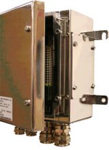
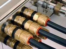
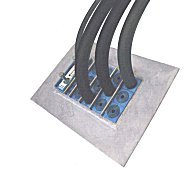
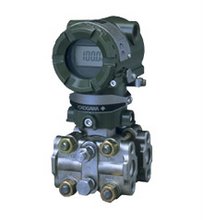

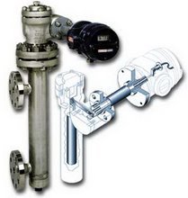

