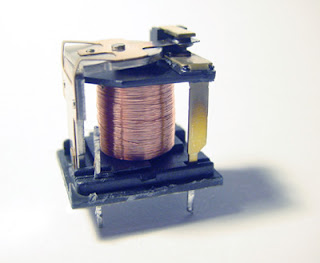
Tuesday, November 13, 2007

Relay

A relay is a simple electromechanical switch made up of an electromagnet and a set of contacts. Relays are found hidden in all sorts of devices. In fact, some of the first computers ever built used relays to implement Boolean gates.

An open relay

Mechanical Relay

Mechanical Switching - Relays
A relay consists of an electromagnet (a coil around a iron bar) that can automatically cause one or more switches to move between to contacts. When current is applied to the electomagnet the switch moves towards the magnet, otherwise the switch is in its "normal" position. By wiring one of the switches into the electromagnetic circuit the relay can be made to remember and thus act as a storage device. In general a relay can be used to make other switches in second and third circuits to move.


From http://www.howstuffworks.com

A relay is so-called since it "relays" or copies an action at one point to another. With simple modifications a relay can duplicate a single action into multiple copies, and even remember an action, thus creating a simple memory device.

Wednesday, September 19, 2007

Cable Outer Sheath PVC vs PE

Polyvinyl Chloride (PVC)

Polyvinyl chloride is basically a hard thermoplastic, but by blending with certain plasticisers a range of general purpose flexible cable compounds of varying degrees of softness can be produced. By the use of selected plasticisers and other additives, grades of PVC can be made which are suitable for either hot or cold ambient temperatures.

Properties

Polyvinyl chloride is a good general purpose thermoplastic. It has good mechanical and ageing properties, and excellent resistance to ozone and weather. It is preferable to pigment it with carbon black to obtain optimum resistance to the effects of sunlight.

Cables insulated and sheathed with PVC will operate satisfactorily when exposed to or immersed in salt or fresh water. Standard PVC compounds are reasonably flame retardant and this property can be improved by special compounding techniques. In general PVC has good resistance to chemicals but affected by solvents and some oils which tend to leach out of the plasticiser and thus cause embrittlement. The so-called 'Heat resisting' grades of PVC have good ageing characteristics at elevated temperatures, but suffer in common with general purpose grades of the tendency to deform under pressure as the temperatures approaches the melting point of the PVC (approx. 130°C). The insulation resistance of PVC is lower than that of some plastics but more than adequate for most wiring applications.

Compared with elastomers, PVC and other thermoplastic materials are susceptible to temperature variations, and they become progressively less flexible as the ambient temperature is lowered.

In general PVC cables should not be installed when the temperature is below 0°C unless the cables have been stored above this temperature for the previous 24 hours. Failure to observe this precaution may result in cracking or shattering of the PVC.

Uses

PVC is used extensively for general wiring cables, low voltage mains cable, domestic flexibles, telephone cable and instrument wiring. It is widely used as a corrosion resistant coating over lead and aluminium sheathed cables.

The maximum continuous operating temperature of general purpose compounds is specified as 70°C and for heat resisting grades as 85°C.

Polyethylene (Polythene)

Polyethylene is a thermoplastic obtained by the polymerisation of ethylene. Depending on the particular polymerisation technique used, polyethylene of varying densities and molecular weight can be produced, and these can therefore be broadly classified as either low or high density polyethylene.

Properties

Polyethylene has extremely good electrical characteristics and excellent resistance to water, chemicals and some solvents. However, it has only moderate resistance to oils and has the disadvantage of being flammable. The low temperature properties of polyethylene are good. It is customary to pigment with carbon black both high and low density polyethylene, to improve their resistance to weather. Polyethylene is an excellent insulation for high voltage cables, but when extruding thick layers of dielectric, care has to be taken to prevent the inclusion of voids during this process. Polyethylene has a melting point of about 110°C-115°C which is a serious disadvantage for cables liable to be subjected to short circuit and overload conditions; this is one of the reasons why the use of this material has discontinued for the insulation of general wiring cables.

Uses

Polyethylene is extensively used either in the solid or expanded form for the insulation of communication cables. One major application is for the insulation of coaxial cable for television downleads, and another is for the insulation of multicore telephone cables where its excellent electrical properties enable a thin small radial wall of insulation to be employed. Polyethylene is used for submarine cables and in some types of high voltage cables. High density polyethylene can be used as an external sheath on cables to provide corrosion protection.

The recommended continuous operating temperature of polyethylene is normally stated as 70°C, to allow a factor of safety for overloads up to a maximum temperature of 90°C.

Wednesday, July 18, 2007

COMPARISON OF GRP/FRP CABLE TRAYS V/S METAL CABLE TRAYS


1.Corrosion Resistance
GRP/FRP - Excellent corrosion resistance against sea water and most chemical fumes
METAL - Poor corrosion resistance, pitting takes place even in SS or aluminum in sea water. Galvanic Corrosion takes place between Stainless Steel trays and MS supports

2.Hot Working
GRP/FRP -No Hot working, all assembly by Nut & Bolts
METAL -Hot working , welding cutting and joining requires special permission in hazardous areas

3.Light weight
GRP/FRP -
Sp.gr. 1.9, 1/4th that of steel, even lighter than Aluminum(sp.gr.2.8), just one person required to lift a big size cable ladder, so very easy and fast Installation, saving time and money
METAL -Very heavy, 4 times to GRP/FRP, hence crane or 3 people required to lift a cable ladder

4.Fire Retardant
GRP/FRP -
Meets most stringent offshore fire resistance norms as per British, ASTM and UL specifications
METAL -In heavy fire even steel de-shapes and needs replacement

5.Installation Cost
GRP/FRP -
Very low, as lighter in wt hence only one man can lift, and very easy to cut and fabricate at site, thus faster installation and easy site adjustment and modifications
METAL -HIGH, needs 2-3 persons or special equipment to lift, also difficult to cut and refabricate as per site requirement as cutting takes time.

6.Risk of cable damage
GRP/FRP -
Very low, as being plastics have much less hardness and even its sharp edges cannot damage a cable
METAL -When any site modification is done, sharp edges are created in metal which can cause damage to cables and pose risk of current.

7.High insulation ands Safe
GRP/FRP -
No earthing of cable tray is required as it has high Insulation value. In case of any cable stripping, the tray being Insulated is safe for the Humans.
METAL -Earthing is must, hence cost of earthing increases overall cost, which is not generally considered when evaluating.

8.Part consolidation
GRP/FRP -
As GRP/FRP is extruded section, inbuilt ribs for reinforcement, collars for fixing covers are possible in single section
METAL -This is not possible in metal, and if welding is done it looks very bad.

9.U.V. resistance
GRP/FRP -
All GRP/FRP cable Trays are made from very high U.V. additives, in addition to special surfacing Veils for glass blooming prevention, and carbon black for additional U.V protection
METAL -N/A

10.Antistatic
GRP/FRP - Cable trays are available in antistatic option as well for oil hazardous areas on demand, thus safe even in hydrocarbon atmosphere.
METAL -N/A

11.First Time COST
GRP/FRP - FRP/GRP cable trays are competitive to SS trays with all above advantages
METAL -SS trays are very costly compared to GRP/FRP Trays

FRP or GRP Cable Ladder/Tray

General
Known as glass-reinforced plastic (GRP) in Britain, fibre-reinforced plastic (FRP) in the USA, or by the trade name fibreglass (after the manufacturing company Fibreglass Ltd.), GRP has been used for a wide range of applications from car body panels and boat hulls to furniture and tennis rackets. It has the virtue of a good weight to strength ratio, rust resistance, and ability to be moulded in a wide variety of ways. It became increasingly widely used in the post-Second World War period, a pioneering design being the celebrated DAR Armchair by Charles and Ray Eames for the 1948 Low-Cost Furniture Design Competition at the Museum of Modern Art in New York. Very much paralleled by the organic forms found in much contemporary product, train, and automobile design in Italy, the flowing, sculptural form of the seat (supported on a metal frame) expressed the creative possibilities of the new medium. These were realized in subsequent designs such as Eero Saarinen's elegant Tulip armchair of 1956. Verner Panton was another designer to explore the expressive qualities of the medium in his moulded, cantilevered chair of 1960 first manufactured in West Germany. Many furniture designs first manufactured in GRP have subsequently been manufactured in ABS plastic. Early use of GRP in automobile manufacture included the roof of the Citroen DS (1955) and the body panels of the Chevrolet Corvette (1953). From the 1970s improved production processes engendered more widespread uses in architecture and interior design, whether in terms of weather resistant details and services or bathrooms.


Definition of FRP Composites


Not all plastics are composites. In fact, the majority of plastics today are pure plastic, like toys and soda bottles. When additional strength is needed, many types of plastics can be reinforced (usually with reinforcing fibers). This combination of plastic and reinforcement can produce some of the strongest materials for their weight that technology has ever developed...and the most versatile.

Therefore, the definition of a fiber-reinforced polymer (FRP) composite is:
A combination of

- a polymer (plastic) matrix (either a thermoplastic or thermoset resin, such as polyester, isopolyester, vinyl ester, epoxy, phenolic)

- a reinforcing agent such as glass, carbon, aramid or other reinforcing material


such that there is a sufficient aspect ratio (length to thickness) to provide a discernable reinforcing function in one or more directions. FRP composite may also contain:

- fillers

- additives

- core materials


that modify and enhance the final product. The constituent elements in a composite retain their identities (they do not dissolve or merge completely into each other) while acting in concert to provide a host of benefits ideal for structural applications including:

High Strength and Stiffness Retention - composites can be designed to provide a wide range of mechanical properties including tensile, flexural, impact and compressive strengths. And, unlike traditional materials, composites can have their strengths oriented to meet specific design requirements of an application.

-Light Weight/Parts Consolidation - FRP composites deliver more strength per unit of weight than most metals. In fact, FRP composites are generally 1/5th the weight of steel. The composite can also be shaped into one complex part, often times replacing assemblies of several parts and fasteners. The combination of these two benefits makes FRP composites a powerful material system- structures can be partially or completely pre-fabricated at the manufacturer's facility, delivered on-site and installed in hours.

-Creep (Permanent Deflection Under Long Term Loading) - The addition of the reinforcement to the polymer matrix increases the creep resistance of the properly designed FRP part. Creep will not be a significant issue if the loads on the structure are kept below appropriate working stress levels.

-Resistance to Environmental Factors - Composites display excellent resistance to the corrosive effects of:
-Freeze-thaw: because composites are not attacked by galvanic corrosion and have low water absorption, they resist the destructive expansion of freezing water.

-Weathering and Ultra-Violet Light: FRP composite structures designed for weather exposure are normally fabricated with a surface layer containing a pigmented gel coat or have an ultraviolet (UV) inhibitor included as an additive to the composite matrix. Both methods provide protection to the underlying material by screening out UV rays and minimizing water absorption along the fiber/resin interface.

-Chemicals and Temperature: Composites do not rust or corrode and can be formulated to provide long-term resistance to nearly every chemical and temperature environment. Of particular benefit, is composites ability to successfully withstand the normally destructive effects of de-icing salts and/or saltwater spray of the ocean.


-Fire Performance of Composites - FRP composites can burn under certain conditions. Composites can be designed to meet the most stringent fire regulations by the use of special resins and additives. Properly designed and formulated composites can offer fire performance approaching that of most metals.

Wednesday, July 4, 2007

Proses membuat Instrument Location Plan

Langkah-langkah untuk menghasilkan Instrument Location Plan secara manual

1. perlu dapatkan Equipment Layout sebagai background
2. dapatkan Piping General Arrangement (GA) untuk mendapatkan kedudukan Instrument tapping point
3. Information dari Piping GA dipindahkan ke Equipment Layout
4. P&ID digunakan untuk menyemak / memastikan segala process instrument dilakarkan diatas Instrument Location Plan

Langkah-langkah untuk menghasilkan Instrument Location Plan dengan menggunakan Model 3D

1. perlu dapatkan Equipment Layout sebagai background
2. Instrument Tapping point dan Instrument Location perlu di “extract” dari Model 3D dan di”superimpose”kan keatas Equipment Layout.
3. P&ID digunakan untuk menyemak / memastikan segala process instrument dilakarkan diatas Instrument Location Plan

Sunday, June 24, 2007

Wiring Diargram

Tujuan utama wiring diagram adalah untuk memberi panduan kepada site technician untuk menjalankan kerja pendawaian dan termination. Semestinya site technician mengharapkan satu drawing yang mempunyai semua maklumat yang deperlukan olehnya dalam bentuk yang jelas dan mudah difahami.

Point-to-point wiring diagram adalah perlu untuk membantu technician yang tidak mahir atau kurang pengalaman melakukan kerja termination dengan betul dan tanpa was-was. Drawing untuk cable termination di Control panel atau terminal box, thermocouple connections dekat JB atau interconnection instrument di belakang panel.

Didalam wiring diagram maklumat berikut mestilah dimasukan:
· Terminal number
· Wire number
· Cable number
· JB/ Cabinet/Panel tag
· Warna wire

Maklumat lain jika dirasakan boleh membantu kerja technician maka perlulah dimasukan.

Wiring diagram adalah berbeza dengan schematic diagram. Wiring diagram menunjukan susun atur secara fizikal tanpa memberi penekanan kepada fungsi satu-satu signal. Manakala schematic diagram lebih menekankan kepada fungsi sesuatu system.

Wednesday, June 20, 2007

Cable Block Diagram

Cable Block merupakan satu cara untuk menerangkan hubungkait keseluruhan cable yang terdapat dalam Process Plant.
Ia perlu dihasilkan dengan penuh tanggungjawab bagi memastikan ia dapat difahami dan diterjemahkan dengan mudah oleh setiap orang yang melihatnya.

Ia merupakan pemudah cara untuk menyemak setiap cable yang terdapat dalam sistem kawalan (DCS/IPS/FGS, dsbnya) , antara fakta yg perlu ada ialah:
· Cable Type
· Cable Size
· Originate
· Destination
· Maklumat goegrafi yang jelas

Bagaimana hendak menghasilkan Cable block Diagram:
· Perlu memahami system secara keseluruhan
· Perlu memahami jenis signal yang digunakan
· Perlu tahu jenis cable yang hendak digunakan
· Perlu tahu destinasi signal dan punca signal
· Perlu tahu kedudukkan setiap komponen dengan jelas

Tuesday, June 19, 2007

THE 4-20mA CURRENT LOOP

THE 4-20mA CURRENT LOOP
The 4-2OmA current loop has been with us for so longthat it's become rather taken for granted in the industrialand process sectors alike. Its popularity comes from itsease of use and its performance. However, just becausesomething is that ubiquitous doesn't mean we're allnecessarily getting the best out of our current loops.
A big benefit of the current loop is its simple wiring justthe two wires. The supply voltage and measuring currentare supplied over the same two wires. Zero offset of thebase current (ie. 4mA) makes cable break detection simple:if the current suddenly drops to zero, you have a cable break.In addition, the current signal is immune to any stray electricalinterference, and a current signal can be transmitted overlong distances.


Typical wiring for current output transducer.
You can think of the current loop itself as being analogousto a water system. You have a hose pipe (the wires) anda source tap (the power supply). You have a spray gunthat regulates the flow (the transducer). You can haveother equipment on the line, but it all has to be connectedtogether in a ring Ioop. The more holes (devices) you haveon the hose pipe, the higher the pressure will be requiredfrom the tap. Relating all that back to the current loop,you see a power supply, a transducer and one or morepieces of instrumentation all connected together in a ring.
You'll often hear things referred to as being either activeor passive. Some instruments have an active output whichincludes both the control of the current in the loop as wellas provide the supply voltage. This is typically specifiedas being a 4-20mA output into 10-750 Ohms, or somethingsimilar. A passive input would be a simple resistor input thathas a voltage drop to be factored into the equation oncethe supply voltage is chosen. This is typically specified asa 4-20mA input into 10 Ohm.
Working out the power supply requirement is a simple matterof adding up all the units in the loop at maximum currentof 20mA. As an example, suppose you have a sensor'regulator' which requires minimum 12V DC and instrumentationof 10 Ohm input:
10 Ohm x 20mA = 0.2V
So, for this circuit, a 12.2V minimum supply is required, thesensor's maximum voltage might be specified at 30V, so a24V supply would be all the circuit requirements with sparecapacity to boot.
In order to measure the current loop it is necessary to breakthe loop and insert a current meter into it. You can alsomeasure the voltage across the various components by inthe loop, such as the voltage out of the power supply, thevoltage over a sensor, and the voltages over the variouspieces of instrumentation. This information will give you agood picture of what is happening within the loop.


Multi-instrument 4-20mA current loop with panel meter,chart recorder, computers, etc.
A question which is sometimes asked is whether it is possibleto use single power supply over several loops. This is possible,but you have to ensure that the power supply can give enoughcurrent to meet the needs of multiple loops. It is also thecase that the current loops will have the same zero negativereference, which can cause a ground loop. In addition,interference from one loop can affect all the other loopsdriven from the one supply.
This article is printed with the kind permission ofMorten Moller, who runs an internet support andconsultancy business and can be contacted atmorten@askmorten.co.ukHis website is at http://www.askmorten.co.uk/

Installation Detail/Hook-up

Installation Detail/Hook-up

Installation Detail atau sketch perlu memaparkan apa yang diperlukan untuk memasang sesuatu instrument.

Ini termasuk kesemua bahan (material) yang yang diperlukan untuk melengkapkan satu proses pemasangan (installation).
Maklumat dari pihak vendor adalah amat perlu bagi memastikan segala bahan yang diperlukan adalah sesuai dan sepadan dengan saiz connection yang diperlukan oleh instrument.

Designer jga perlu mengandaikan situasi dimana Tukang Pasang tidak biasa atau pertama kali memasang Instrument tersebut.

Location Plan/Plot Plan

Location Plan/Plot Plan
Instrument Location plan memasukan semua Instrument yang berhubungkait dengan instrument lain.
Selalunya terbahagi kepada dua fungsi iaitu:
1. Untuk kegunaan pemasangan (Installation) Instrument dan pemasangan tiub untuk Process connection dan tiub untuk signal pneumatik. Ini selalunya melibatkan kerja-kerja paip dan tiub (pipe fitter). Jadi rajah Location Plan dan Tube routing layout perlu dihasilkan.
2. Untuk kegunaan pendawaian. Ini melibatkan kerja-kerja perancangan utk laluan kabel dan lokasi kotak pencawang (JB). Jadi rajah Cable Tray/Ladder perlu dihasilkan untuk panduan pemasangan Cable Ladder/Tray. Manakala rajah Cable Routing pula diperlukan sebagai panduan kerja pendawaian dilakukan dengan cekap.

Rajah dasar (back ground) biasanya diambil dari rajah Piping atau Equipment Layout.

Saiz Helaian-ISO

Saiz helaian mengikut ISO

Saiz Helaian -ANSI

Saiz helaian mengikut ANSI

Friday, June 8, 2007


Wednesday, June 6, 2007

Wire & Cable Cross reference

Monday, May 28, 2007

Description of BS 6883 Power, control and instrument cables.

Description of BS 6883 Power, control and instrument cables.

http://www.bs6883.net/

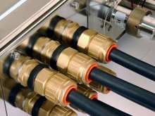
BS6883 is the British (and also an international) industry standard for the Offshore Oil and Gas, Ship building & Marine Industries.

These cables are certified by Lloyds and DNV in accordance with ISO 9001 AND 14001.

The BS6883 cables are flameproof and when a mica glass tape is applied over the conductors are fire resistant.

Construction is similiar to other industry standards (such as NEK606 and IEEE 1580 type P) however variations in the construction of BS6883 and other products as listed in the industry relate to the insulation, screening, braiding, bedding and sheathing compounds.

The Conductors of BS6883 cables are constructed with circular metal coated copper conductors and comply with BS 6360 for class 2 or class5.

Where the cables comply to BS7917 fire resistant a mica glass tape is applied over the conductor.

BS 6883 conductors are insulated with EPR and comply with BS 7655.

BS 6883 conductor insulation colours/and or numbers differ from both NEK606 and IEEE 1580 typeP).

BS 6883 sheathing compounds for both inner and outer cables are typically EVA (halogen free) and or CSP subject to clients requirements, both of which can be used offshore and comply with industry standards.

BS 6883 armoured cables have either galvanised steel wire braid (GSWB) or in the case of single core cables a phosphor bronze (BPWB) ot tinned copper wire (TCWB).

Standard outside sheath colours are Black for power and control, Grey for instrument, Red for medium voltage.

BS 6883 Instrument cables are screened with an Aluminium mylar tape in contact with a tinned copper drain wire.

BS5308 Cables

BS5308 Cables


BS5308 Part 1 / Type 1 Unarmoured Construction

1. Plain annealed copper wire conductors to BS 6360

2. Polyethene insulation to BS 6234

3 Individual pair screen (optional):-
a) Aluminium/polyester tape, metallic side down, in contact with minimum 0.5mm2 tinned copper drain wire
b) Polyester isolating tape(s) numbered for identification

4 Polyester binder tape

5 Collective screen (optional) - Aluminium/polyester tape, metallic side down, in contact with minimum 0.5mm2 tinned copper drain wire

6 PVC sheath to BS 7655


BS5308 Part 1 / Type 2 Armoured Construction

1 Plain annealed copper wire conductors to BS 6360

2 Polyethene insulation to BS 6234

3 Individual pair screen (optional):-
a) Aluminium/polyester tape, metallic side down, in contact with minimum 0.5mm2 tinned copper drain wire
b) Polyester isolating tape(s) numbered for identification

4 Polyester binder tape

5 Collective screen (optional) - Aluminium/polyester tape, metallic side down, in contact with minimum 0.5mm2 tinned copper drain wire

6 Black polyethylene bedding to BS 6234

7 Single layer galvanised steel wire armour to BS EN 10257-1

8 PVC sheath to BS 7655


BS5308 Part 2 / Type 1 (unarmoured)

1 Plain annealed copper wire conductors to BS 6360

2 PVC to BS 7655

3 Individual pair screen (optional):-
a) Aluminium/polyester tape, metallic side down, in contact with minimum 0.5mm2 tinned copper drain wire
b) Polyester isolating tape(s) numbered for identification

4 Polyester binder tape

5 Collective screen (optional) - Aluminium/polyester tape, metallic side down, in contact with minimum 0.5mm2 tinned copper drain wire

6 PVC sheath to BS 7655


BS5308 Part 2 / Type 2 (armoured)

1 Plain annealed copper wire conductors to BS 6360

2 PVC to BS 7655

3 Individual pair screen (optional):-
a) Aluminium/polyester tape, metallic side down, in contact with minimum 0.5mm2 tinned copper drain wire
b) Polyester isolating tape(s) numbered for identification

4 Polyester binder tape

5 Collective screen (optional) - Aluminium/polyester tape, metallic side down, in contact with minimum 0.5mm2 tinned copper drain wire

6 PVC bedding to BS 7655

7 Single layer galvanised steel wire armour to BS EN 10257-1

8 PVC sheath to BS 7655

Sunday, May 27, 2007

NEMA Enclosure Types

NEMA PC Enclosure Types

This document provides general information on the definitions of NEMA Enclosure Types
Definitions[From NEMA 250-1997]
In Non-Hazardous Locations, the specific enclosure Types, their applications, and the environmental conditions they are designed to protect against, when completely and properly installed, are as follows:
Type 1 - The unit is constructed for indoor use to provide a degree of protection to personnel against incidental contact with the enclosed equipment and to provide a degree of protection against falling dirt.
Type 2 - Enclosure constructed for indoor use to provide a degree of protection to personnel against incidental contact with the enclosed equipment, to provide a degree of protection against falling dirt, and to provide a degree of protection against dripping and light splashing of liquids.
Type 3 - Pc cabinet constructed for either indoor or outdoor use to provide a degree of protection to personnel against incidental contact with the enclosed equipment; to provide a degree of protection against falling dirt, rain, sleet, snow, and windblown dust; and that will be undamaged by the external formation of ice on the enclosure.
Type 3R - Cabinet constructed for either indoor or outdoor use to provide a degree of protection to personnel against incidental contact with the enclosed equipment; to provide a degree of protection against falling dirt, rain, sleet, and snow; and that will be undamaged by the external formation of ice on the enclosure.
Type 3S - Computer cabinet constructed for either indoor or outdoor use to provide a degree of protection to personnel against incidental contact with the enclosed equipment; to provide a degree of protection against falling dirt, rain, sleet, snow, and windblown dust; and in which the external mechanism(s) remain operable when ice laden.
Type 4 - Computer enclosures constructed for either indoor or outdoor use to provide a degree of protection to personnel against incidental contact with the enclosed equipment; to provide a degree of protection against falling dirt, rain, sleet, snow, windblown dust, splashing water, and hose-directed water; and that will be undamaged by the external formation of ice on the enclosure.
Type 4X - protection unit constructed for either indoor or outdoor use to provide a degree of protection to personnel against incidental contact with the enclosed equipment; to provide a degree of protection against falling dirt, rain, sleet, snow, windblown dust, splashing water, hose-directed water, and corrosion; and that will be undamaged by the external formation of ice on the enclosure.
Type 5 - computer enclosure constructed for indoor use to provide a degree of protection to personnel against incidental contact with the enclosed equipment; to provide a degree of protection against falling dirt; against settling airborne dust, lint, fibres, and flyings; and to provide a degree of protection against dripping and light splashing of liquids.
Type 6 - PC Enclosures constructed for either indoor or outdoor use to provide a degree of protection to personnel against incidental contact with the enclosed equipment; to provide a degree of protection against falling dirt; against hose-directed water and the entry of water during occasional temporary submersion at a limited depth; and that will be undamaged by the external formation of ice on the enclosure.
Type 6P - cabinet constructed for either indoor or outdoor use to provide a degree of protection to personnel against incidental contact with the enclosed equipment; to provide a degree of protection against falling dirt; against hose-directed water and the entry of water during prolonged submersion at a limited depth; and that will be undamaged by the external formation of ice on the enclosure.
Type 12 - computer cabinet constructed (without knockouts) for indoor use to provide a degree of protection to personnel against incidental contact with the enclosed equipment; to provide a degree of protection against falling dirt; against circulating dust, lint, fibres, and flyings; and against dripping and light splashing of liquids.
Type 12K - Enclosures constructed (with knockouts) for indoor use to provide a degree of protection to personnel against incidental contact with the enclosed equipment; to provide a degree of protection against falling dirt; against circulating dust, lint, fibres, and flyings; and against dripping and light splashing of liquids.
Type 13 - Enclosures constructed for indoor use to provide a degree of protection to personnel against incidental contact with the enclosed equipment; to provide a degree of protection against falling dirt; against circulating dust, lint, fibres, and flyings; and against the spraying, splashing, and seepage of water, oil, and non-corrosive coolants.

PC Enclosure Classification Designations
IEC Publication 60529 Classification of Degrees of Protection Provided by Enclosures provides a system for specifying the enclosures of electrical equipment on the basis of the degree of protection provided by the enclosure. IEC 60529 does not specify degrees of protection against mechanical damage of equipment, risk of explosions, or conditions such as moisture (produced for example by condensation), corrosive vapours, fungus, or vermin. The NEMA Standard for Enclosures for Electrical Equipment does test for environmental conditions such as corrosion, rust, icing, oil, and coolants. For this reason, and because the test and evaluations for other characteristics are not identical, the IEC Enclosure Classification Designations cannot be exactly equated with the enclosure Type numbers in this Standard.
The IEC designation consists of the letters IP followed by two numerals. The first characteristic numeral indicates the degree of protection provided by the enclosure with respect to persons and solid foreign objects entering the enclosure. The second characteristic numeral indicates the degree of protection provided by the enclosure with respect to the harmful ingress of water.
Table A-1 provides an equivalent conversion from the enclosure Type numbers in this Standard to the IEC Enclosure Classification Designations. The enclosure type numbers meet or exceed the test requirements for the associated IEC Classification; for this reason Table A-1 cannot be used to convert from IEC Classifications to enclosure Type numbers.
Table A-1 [From NEMA 250-1997]
Conversion of Enclosure Type numbers to IEC Classification Designations
Cannot be used to convert IEC Classification Designations to NEMA Type numbers


Enclosure

NEMA -IEC IP


1 -IP10

2 -IP11

3 -IP54

3R- IP14

3S -IP54

4 and 4X- IP56

5 -IP52

6 AND 6P- IP67

12 AND 12K -IP52

13- IP54

How Fiber Optics Work

How Fiber Optics Work
by Craig C. Freudenrich, Ph.D.
http://electronics.howstuffworks.com/fiber-optic.htm

1.Introduction to How Fiber Optics Work

You hear about fiber-optic cables whenever people talk about the telephone system, the cable TV system or the Internet. Fiber-optic lines are strands of optically pure glass as thin as a human hair that carry digital information over long distances. They are also used in medical imaging and mechanical engineering inspection.

In this article, we will show you how these tiny strands of glass transmit light and the fascinating way that these strands are made.

2.What are Fiber Optics?

Fiber optics (optical fibers) are long, thin strands of very pure glass about the diameter of a human hair. They are arranged in bundles called optical cables and used to transmit light signals over long distances.


Parts of a single optical fiber

If you look closely at a single optical fiber, you will see that it has the following parts:

  • Core - Thin glass center of the fiber where the light travels
  • Cladding - Outer optical material surrounding the core that reflects the light back into the core
  • Buffer coating - Plastic coating that protects the fiber from damage and moisture
Hundreds or thousands of these optical fibers are arranged in bundles in optical cables. The bundles are protected by the cable's outer covering, called a jacket.

Optical fibers come in two types:

  • Single-mode fibers
  • Multi-mode fibers
See Tpub.com: Mode Theory for a good explanation.

Single-mode fibers have small cores (about 3.5 x 10⁻⁴ inches or 9 microns in diameter) and transmit infrared laser light (wavelength = 1,300 to 1,550 nanometers). Multi-mode fibers have larger cores (about 2.5 x 10⁻³ inches or 62.5 microns in diameter) and transmit infrared light (wavelength = 850 to 1,300 nm) from light-emitting diodes (LEDs).

Some optical fibers can be made from plastic. These fibers have a large core (0.04 inches or 1 mm diameter) and transmit visible red light (wavelength = 650 nm) from LEDs.

3.How Does an Optical Fiber Transmit Light?

Suppose you want to shine a flashlight beam down a long, straight hallway. Just point the beam straight down the hallway -- light travels in straight lines, so it is no problem. What if the hallway has a bend in it? You could place a mirror at the bend to reflect the light beam around the corner. What if the hallway is very winding with multiple bends? You might line the walls with mirrors and angle the beam so that it bounces from side-to-side all along the hallway. This is exactly what happens in an optical fiber.


Diagram of total internal reflection in an optical fiber

The light in a fiber-optic cable travels through the core (hallway) by constantly bouncing from the cladding (mirror-lined walls), a principle called total internal reflection. Because the cladding does not absorb any light from the core, the light wave can travel great distances. However, some of the light signal degrades within the fiber, mostly due to impurities in the glass. The extent that the signal degrades depends on the purity of the glass and the wavelength of the transmitted light (for example, 850 nm = 60 to 75 percent/km; 1,300 nm = 50 to 60 percent/km; 1,550 nm is greater than 50 percent/km). Some premium optical fibers show much less signal degradation -- less than 10 percent/km at 1,550 nm.

4. A Fiber-Optic Relay System

To understand how optical fibers are used in communications systems, let's look at an example from a World War II movie or documentary where two naval ships in a fleet need to communicate with each other while maintaining radio silence or on stormy seas. One ship pulls up alongside the other. The captain of one ship sends a message to a sailor on deck. The sailor translates the message into Morse code (dots and dashes) and uses a signal light (floodlight with a venetian blind type shutter on it) to send the message to the other ship. A sailor on the deck of the other ship sees the Morse code message, decodes it into English and sends the message up to the captain.

Now, imagine doing this when the ships are on either side of the ocean separated by thousands of miles and you have a fiber-optic communication system in place between the two ships. Fiber-optic relay systems consist of the following:

  • Transmitter - Produces and encodes the light signals
  • Optical fiber - Conducts the light signals over a distance
  • Optical regenerator - May be necessary to boost the light signal (for long distances)
  • Optical receiver - Receives and decodes the light signals

Transmitter
The transmitter is like the sailor on the deck of the sending ship. It receives and directs the optical device to turn the light "on" and "off" in the correct sequence, thereby generating a light signal.

The transmitter is physically close to the optical fiber and may even have a lens to focus the light into the fiber. Lasers have more power than LEDs, but vary more with changes in temperature and are more expensive. The most common wavelengths of light signals are 850 nm, 1,300 nm, and 1,550 nm (infrared, non-visible portions of the spectrum).

Optical Regenerator
As mentioned above, some signal loss occurs when the light is transmitted through the fiber, especially over long distances (more than a half mile, or about 1 km) such as with undersea cables. Therefore, one or more optical regenerators is spliced along the cable to boost the degraded light signals.

An optical regenerator consists of optical fibers with a special coating (doping). The doped portion is "pumped" with a laser. When the degraded signal comes into the doped coating, the energy from the laser allows the doped molecules to become lasers themselves. The doped molecules then emit a new, stronger light signal with the same characteristics as the incoming weak light signal. Basically, the regenerator is a laser amplifier for the incoming signal. See Photonics.com: Fiber Amplifiers for more details.

Optical Receiver
The optical receiver is like the sailor on the deck of the receiving ship. It takes the incoming digital light signals, decodes them and sends the electrical signal to the other user's computer, TV or telephone (receiving ship's captain). The receiver uses a photocell or photodiode to detect the light.


5. Advantages of Fiber Optics

Why are fiber-optic systems revolutionizing telecommunications? Compared to conventional metal wire (copper wire), optical fibers are:
  • Less expensive - Several miles of optical cable can be made cheaper than equivalent lengths of copper wire. This saves your provider (cable TV, Internet) and you money.

  • Thinner - Optical fibers can be drawn to smaller diameters than copper wire.

  • Higher carrying capacity - Because optical fibers are thinner than copper wires, more fibers can be bundled into a given-diameter cable than copper wires. This allows more phone lines to go over the same cable or more channels to come through the cable into your cable TV box.

  • Less signal degradation - The loss of signal in optical fiber is less than in copper wire.

  • Light signals - Unlike electrical signals in copper wires, light signals from one fiber do not interfere with those of other fibers in the same cable. This means clearer phone conversations or TV reception.

  • Low power - Because signals in optical fibers degrade less, lower-power transmitters can be used instead of the high-voltage electrical transmitters needed for copper wires. Again, this saves your provider and you money.

  • Digital signals - Optical fibers are ideally suited for carrying digital information, which is especially useful in computer networks.

  • Non-flammable - Because no electricity is passed through optical fibers, there is no fire hazard.

  • Lightweight - An optical cable weighs less than a comparable copper wire cable. Fiber-optic cables take up less space in the ground.

  • Flexible - Because fiber optics are so flexible and can transmit and receive light, they are used in many flexible digital cameras for the following purposes:
Because of these advantages, you see fiber optics in many industries, most notably telecommunications and computer networks. For example, if you telephone Europe from the United States (or vice versa) and the signal is bounced off a communications satellite, you often hear an echo on the line. But with transatlantic fiber-optic cables, you have a direct connection with no echoes.

6.How Are Optical Fibers Made?

Now that we know how fiber-optic systems work and why they are useful -- how do they make them? Optical fibers are made of extremely pure optical glass. We think of a glass window as transparent, but the thicker the glass gets, the less transparent it becomes due to impurities in the glass. However, the glass in an optical fiber has far fewer impurities than window-pane glass. One company's description of the quality of glass is as follows: If you were on top of an ocean that is miles of solid core optical fiber glass, you could see the bottom clearly.

Making optical fibers requires the following steps:

  1. Making a preform glass cylinder
  2. Drawing the fibers from the preform
  3. Testing the fibers

Making the Preform Blank
The glass for the preform is made by a process called modified chemical vapor deposition (MCVD).


Image courtesy Fibercore Ltd.
MCVD process for making the preform blank

In MCVD, oxygen is bubbled through solutions of silicon chloride (SiCl4), germanium chloride (GeCl4) and/or other chemicals. The precise mixture governs the various physical and optical properties (index of refraction, coefficient of expansion, melting point, etc.). The gas vapors are then conducted to the inside of a synthetic silica or quartz tube (cladding) in a special lathe. As the lathe turns, a torch is moved up and down the outside of the tube. The extreme heat from the torch causes two things to happen:


Photo courtesy Fibercore Ltd.
Lathe used in preparing
the preform blank

  • The silicon and germanium react with oxygen, forming silicon dioxide (SiO2) and germanium dioxide (GeO2).

  • The silicon dioxide and germanium dioxide deposit on the inside of the tube and fuse together to form glass.

The lathe turns continuously to make an even coating and consistent blank. The purity of the glass is maintained by using corrosion-resistant plastic in the gas delivery system (valve blocks, pipes, seals) and by precisely controlling the flow and composition of the mixture. The process of making the preform blank is highly automated and takes several hours. After the preform blank cools, it is tested for quality control (index of refraction).

Drawing Fibers from the Preform Blank
Once the preform blank has been tested, it gets loaded into a fiber drawing tower.


Diagram of a fiber drawing tower used to draw optical glass fibers from a preform blank

The blank gets lowered into a graphite furnace (3,452 to 3,992 degrees Fahrenheit or 1,900 to 2,200 degrees Celsius) and the tip gets melted until a molten glob falls down by gravity. As it drops, it cools and forms a thread.


The operator threads the strand through a series of coating cups (buffer coatings) and ultraviolet light curing ovens onto a tractor-controlled spool. The tractor mechanism slowly pulls the fiber from the heated preform blank and is precisely controlled by using a laser micrometer to measure the diameter of the fiber and feed the information back to the tractor mechanism. Fibers are pulled from the blank at a rate of 33 to 66 ft/s (10 to 20 m/s) and the finished product is wound onto the spool. It is not uncommon for spools to contain more than 1.4 miles (2.2 km) of optical fiber.

Testing the Finished Optical Fiber


Photo courtesy Corning
Finished spool of optical fiber
The finished optical fiber is tested for the following:
  • Tensile strength - Must withstand 100,000 lb/in2 or more

  • Refractive index profile - Determine numerical aperture as well as screen for optical defects

  • Fiber geometry - Core diameter, cladding dimensions and coating diameter are uniform

  • Attenuation - Determine the extent that light signals of various wavelengths degrade over distance

  • Information carrying capacity (bandwidth) - Number of signals that can be carried at one time (multi-mode fibers)

  • Chromatic dispersion - Spread of various wavelengths of light through the core (important for bandwidth)

  • Operating temperature/humidity range

  • Temperature dependence of attenuation

  • Ability to conduct light underwater - Important for undersea cables
Once the fibers have passed the quality control, they are sold to telephone companies, cable companies and network providers. Many companies are currently replacing their old copper-wire-based systems with new fiber-optic-based systems to improve speed, capacity and clarity.

7. Physics of Total Internal Reflection

When light passes from a medium with one index of refraction (m1) to another medium with a lower index of refraction (m2), it bends or refracts away from an imaginary line perpendicular to the surface (normal line). As the angle of the beam through m1 becomes greater with respect to the normal line, the refracted light through m2 bends further away from the line.

At one particular angle (critical angle), the refracted light will not go into m2, but instead will travel along the surface between the two media (sine [critical angle] = n2/n1 where n1 and n2 are the indices of refraction [n1 is greater than n2]). If the beam through m1 is greater than the critical angle, then the refracted beam will be reflected entirely back into m1 (total internal reflection), even though m2 may be transparent!

In physics, the critical angle is described with respect to the normal line. In fiber optics, the critical angle is described with respect to the parallel axis running down the middle of the fiber. Therefore, the fiber-optic critical angle = (90 degrees - physics critical angle).


Total internal reflection in an optical fiber

In an optical fiber, the light travels through the core (m1, high index of refraction) by constantly reflecting from the cladding (m2, lower index of refraction) because the angle of the light is always greater than the critical angle. Light reflects from the cladding no matter what angle the fiber itself gets bent at, even if it's a full circle!

Because the cladding does not absorb any light from the core, the light wave can travel great distances. However, some of the light signal degrades within the fiber, mostly due to impurities in the glass. The extent that the signal degrades depends upon the purity of the glass and the wavelength of the transmitted light (for example, 850 nm = 60 to 75 percent/km; 1,300 nm = 50 to 60 percent/km; 1,550 nm is greater than 50 percent/km). Some premium optical fibers show much less signal degradation -- less than 10 percent/km at 1,550 nm.


Cable Tray

Cable Tray


A cable tray system, according to the US National Electrical Code, is "a unit or assembly of units or sections and associated fittings forming a rigid structural system used to securely fasten or support cables and raceways." Cable trays are used to hold up and distribute cables.

Types

  • Ladder
  • Solid Bottom
  • Trough
  • Channel
  • Wire Mesh
  • Single Rail

Materials used

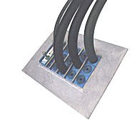
The choice of materials is a matter of the physical and mechanical properties produced by each, compared against the intended function, as well as the environment, in which the trays are to be installed.

Wednesday, May 9, 2007

Introduction to AutoCAD

AutoCAD is a suite of CAD software products for 2- and 3-dimensional design and drafting, developed and sold by Autodesk, Inc.. The original concept of AutoCAD in the 1980s was to promote customization and feature extensibility, and was what made it especially appealing to customers. Most contemporary CAD products at that time offered little if any customization capability and most were far more expensive.
Modern AutoCAD includes a full set of basic solid modeling and 3D tools, but lacks some of the more advanced capabilities of solid modeling applications. AutoCAD can be used as a platform for other products such as Bentley AutoPLANT and COADE CADWORX. AutoCAD is a vector graphics drawing program. It uses primitive entities — such as lines, polylines, circles, arcs, and text — as the foundation for more complex objects.
AutoCAD supports a number of application programming interfaces (APIs) for customization and automation. These include AutoLISP, Visual LISP, VBA, .NET and ObjectARX. ObjectARX is a C++ class library, which was also the base for products extending AutoCAD functionality to specific fields, to create products such as Autodesk Architectural Desktop, AutoCAD Electrical, or third-party AutoCAD-based applications.
AutoCAD's native file format, DWG, and to a lesser extent, its interchange file format, DXF, have become de facto standards for interchange of CAD data. AutoCAD in later years has adopted another file format known as DWF. These files allow selected DWG drawings to be compiled to one file. This allows distribution of the drawings to those without AutoCAD or similar packages. It also protects the drawings from manipulation by others as the drawings are rasterized inside the DWF file. DWF files can be viewed with a free program from Autodesk called "DWF Viewer" - this program allows users to both view and print DWF files. Another advantage of DWF files is that a large number of drawings can be compiled to a single DWF and be of a very small to reasonble file size for electronic distribution. In 2006, Autodesk estimated the number of active DWG files to be in excess of one billion. In the past, Autodesk has estimated the total number of DWG files in existence to be more than three billion.
AutoCAD currently runs exclusively on Microsoft desktop operating systems. Versions for Unix and Macintosh were released in the 1980s and 1990s, but these were later dropped. AutoCAD can run on an emulator or compatibility layer like Virtual PC or Wine, keeping in mind the performance issues that can arise when working with 3-dimensional objects or large drawings. AutoCAD exists in 14 language localizations, including many European and Asian languages.

Introduction to CAD

From Wikipedia, the free encyclopedia

CAD is used to design, develop and optimize products, which can be goods used by end consumers or intermediate goods used in other products.
CAD is also extensively used in the design of tools and machinery used in the manufacture of components, and in the drafting and design of all types of buildings, from small residential types (houses) to the largest commercial and industrial structures (hospitals and factories).
CAD is mainly used for detailed engineering of 3D models and/or 2D drawings of physical components, but it is also used throughout the engineering process from conceptual design and layout of products, through strength and dynamic analysis of assemblies to definition of manufacturing methods of components.
CAD has become an especially important technology, within CAx, with benefits, such as lower product development costs and a greatly shortened design cycle, because CAD enables designers to lay out and develop their work on screen, print it out and save it for future editing, saving a lot of time on their drawings.
CAD is mainly used for detailed engineering of 3D models and/or 2D drawings of physical components, but it is also used throughout the engineering process from conceptual design and layout of products, through strength and dynamic analysis of assemblies to definition of manufacturing methods of components.

Plant Design Management System

From Wikipedia, the free encyclopedia

PDMS as it is known in the 3D CAD industry, is a customizable, multi-user and multi-discipline, engineer controlled design software package for engineering, design and construction projects in, but not limited to, offshore and onshore oil & gas industry, chemical & process plants, mining, pharmaceutical & food industry, power generation and paper industries.[1]

History
The Computer-Aided Design Centre (or CADCentre) was created in Cambridge UK in 1968 by the UK Ministry of Technology.

Its mission was to develop computer-aided design techniques. The centre carried out much pioneering CAD research, and many of its early staff members went on to become prominent in the worldwide CAD community.

Brothers Dick and Martin Newell are two of the most prominent.
Dick Newell oversaw the creation of the extremely successful Plant Design Management System (PDMS) for 3D process plant design. Along with the Cambridge Science Park, CADCentre was arguably the most important single factor in the transformation of Cambridge into one of the world's high technology centers within in a few short years in the 1980s. CADCentre became a publicly quoted company in 1996 and later changed its name to Aveva.[2]

References:

  1. AVEVA Solutions Limited (2002). Vantage Plant Design Management System (PDMS)
  2. "CADCentre".. (22 November 2006 11:14 UTC). Wikipedia. 89424428

Tuesday, May 8, 2007

Auto Cad Tutorial (Lesson2) in Arabic. Sunstone

What is AutoCad?


CAD is used to design, develop and optimize products, which can be goods used by end consumers or intermediate goods used in other products. CAD is also extensively used in the design of tools and machinery used in the manufacture of components, and in the drafting and design of all types of buildings, from small residential types (houses) to the largest commercial and industrial structures (hospitals and factories).

CAD is mainly used for detailed engineering of 3D models and/or 2D drawings of physical components, but it is also used throughout the engineering process from conceptual design and layout of products, through strength and dynamic analysis of assemblies to definition of manufacturing methods of components.

CAD has become an especially important technology, within CAx, with benefits, such as lower product development costs and a greatly shortened design cycle, because CAD enables designers to lay out and develop their work on screen, print it out and save it for future editing, saving a lot of time on their drawings.

AutoCAD Tutorial - 01