Sunday, June 24, 2007
Wiring Diargram
Point-to-point wiring diagram adalah perlu untuk membantu technician yang tidak mahir atau kurang pengalaman melakukan kerja termination dengan betul dan tanpa was-was. Drawing untuk cable termination di Control panel atau terminal box, thermocouple connections dekat JB atau interconnection instrument di belakang panel.
Didalam wiring diagram maklumat berikut mestilah dimasukan:
· Terminal number
· Wire number
· Cable number
· JB/ Cabinet/Panel tag
· Warna wire
Maklumat lain jika dirasakan boleh membantu kerja technician maka perlulah dimasukan.
Wiring diagram adalah berbeza dengan schematic diagram. Wiring diagram menunjukan susun atur secara fizikal tanpa memberi penekanan kepada fungsi satu-satu signal. Manakala schematic diagram lebih menekankan kepada fungsi sesuatu system.
Wednesday, June 20, 2007
Cable Block Diagram
Ia perlu dihasilkan dengan penuh tanggungjawab bagi memastikan ia dapat difahami dan diterjemahkan dengan mudah oleh setiap orang yang melihatnya.
Ia merupakan pemudah cara untuk menyemak setiap cable yang terdapat dalam sistem kawalan (DCS/IPS/FGS, dsbnya) , antara fakta yg perlu ada ialah:
· Cable Type
· Cable Size
· Originate
· Destination
· Maklumat goegrafi yang jelas
Bagaimana hendak menghasilkan Cable block Diagram:
· Perlu memahami system secara keseluruhan
· Perlu memahami jenis signal yang digunakan
· Perlu tahu jenis cable yang hendak digunakan
· Perlu tahu destinasi signal dan punca signal
· Perlu tahu kedudukkan setiap komponen dengan jelas
Tuesday, June 19, 2007
THE 4-20mA CURRENT LOOP
THE 4-20mA CURRENT LOOP
The 4-2OmA current loop has been with us for so longthat it's become rather taken for granted in the industrialand process sectors alike. Its popularity comes from itsease of use and its performance. However, just becausesomething is that ubiquitous doesn't mean we're allnecessarily getting the best out of our current loops.
A big benefit of the current loop is its simple wiring justthe two wires. The supply voltage and measuring currentare supplied over the same two wires. Zero offset of thebase current (ie. 4mA) makes cable break detection simple:if the current suddenly drops to zero, you have a cable break.In addition, the current signal is immune to any stray electricalinterference, and a current signal can be transmitted overlong distances.

Typical wiring for current output transducer.
You can think of the current loop itself as being analogousto a water system. You have a hose pipe (the wires) anda source tap (the power supply). You have a spray gunthat regulates the flow (the transducer). You can haveother equipment on the line, but it all has to be connectedtogether in a ring Ioop. The more holes (devices) you haveon the hose pipe, the higher the pressure will be requiredfrom the tap. Relating all that back to the current loop,you see a power supply, a transducer and one or morepieces of instrumentation all connected together in a ring.
You'll often hear things referred to as being either activeor passive. Some instruments have an active output whichincludes both the control of the current in the loop as wellas provide the supply voltage. This is typically specifiedas being a 4-20mA output into 10-750 Ohms, or somethingsimilar. A passive input would be a simple resistor input thathas a voltage drop to be factored into the equation oncethe supply voltage is chosen. This is typically specified asa 4-20mA input into 10 Ohm.
Working out the power supply requirement is a simple matterof adding up all the units in the loop at maximum currentof 20mA. As an example, suppose you have a sensor'regulator' which requires minimum 12V DC and instrumentationof 10 Ohm input:
10 Ohm x 20mA = 0.2V
So, for this circuit, a 12.2V minimum supply is required, thesensor's maximum voltage might be specified at 30V, so a24V supply would be all the circuit requirements with sparecapacity to boot.
In order to measure the current loop it is necessary to breakthe loop and insert a current meter into it. You can alsomeasure the voltage across the various components by inthe loop, such as the voltage out of the power supply, thevoltage over a sensor, and the voltages over the variouspieces of instrumentation. This information will give you agood picture of what is happening within the loop.

Multi-instrument 4-20mA current loop with panel meter,chart recorder, computers, etc.
A question which is sometimes asked is whether it is possibleto use single power supply over several loops. This is possible,but you have to ensure that the power supply can give enoughcurrent to meet the needs of multiple loops. It is also thecase that the current loops will have the same zero negativereference, which can cause a ground loop. In addition,interference from one loop can affect all the other loopsdriven from the one supply.
This article is printed with the kind permission ofMorten Moller, who runs an internet support andconsultancy business and can be contacted atmorten@askmorten.co.ukHis website is at http://www.askmorten.co.uk/
Installation Detail/Hook-up
Installation Detail atau sketch perlu memaparkan apa yang diperlukan untuk memasang sesuatu instrument.
Ini termasuk kesemua bahan (material) yang yang diperlukan untuk melengkapkan satu proses pemasangan (installation).
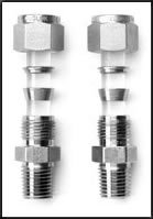
Maklumat dari pihak vendor adalah amat perlu bagi memastikan segala bahan yang diperlukan adalah sesuai dan sepadan dengan saiz connection yang diperlukan oleh instrument.
Designer jga perlu mengandaikan situasi dimana Tukang Pasang tidak biasa atau pertama kali memasang Instrument tersebut.
Location Plan/Plot Plan
Instrument Location plan memasukan semua Instrument yang berhubungkait dengan instrument lain.
Selalunya terbahagi kepada dua fungsi iaitu:
1. Untuk kegunaan pemasangan (Installation) Instrument dan pemasangan tiub untuk Process connection dan tiub untuk signal pneumatik. Ini selalunya melibatkan kerja-kerja paip dan tiub (pipe fitter). Jadi rajah Location Plan dan Tube routing layout perlu dihasilkan.
2. Untuk kegunaan pendawaian. Ini melibatkan kerja-kerja perancangan utk laluan kabel dan lokasi kotak pencawang (JB). Jadi rajah Cable Tray/Ladder perlu dihasilkan untuk panduan pemasangan Cable Ladder/Tray. Manakala rajah Cable Routing pula diperlukan sebagai panduan kerja pendawaian dilakukan dengan cekap.
Rajah dasar (back ground) biasanya diambil dari rajah Piping atau Equipment Layout.


